
Diagrams
Language Namespace : de.itemis.mps.editor.diagram
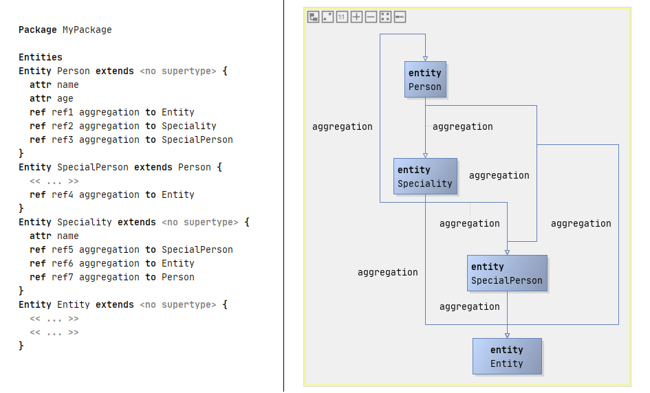
With the diagrams language it is possible to graphically edit your model. The screenshot below shows a graphical diagram model of an example language. The diagram to the right is a graphical representation of the textual model on the left. This example is taken from the de.itemis.mps.editor.diagram.demoentities.sandbox solution.
Download
Download the nightly build of the plugins from the release page.
Examples
The example languages de.itemis.mps.editor.diagram.demolang, de.itemis.mps.editor.diagram.demo.* (link) provide a good overview of the diagram language’s features. Refer to mbeddr.com for more example screenshots. You have to scroll down to Diagrams (de.slisson.mps.editor.diagram) to see these screenshots.
Installation
Extract the downloaded de.itemis.mps.extensions package and copy its content into your local MPS installation directory into the plugins folder (e.g. \JetBrains\MPS 2020.2\plugins). Check the installation by opening MPS, navigate to Settings -> Plugins -> Other Tools and find de.itemis.mps.editor.diagram in there.
Features
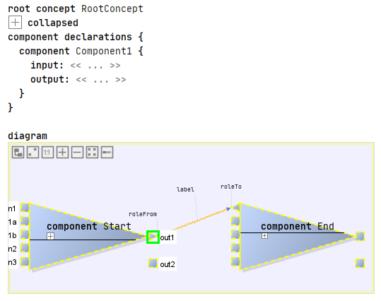
This screenshot shows a few interesting features:
- you can embed diagrams anywhere in “text”
- you can use different shapes (at this point drawn by custom Java code)
- you can use various line styles, the framework supports ports (i.e., connection endpoints on the boxes)
- inside boxes you can use arbitrary MPS text (or other) editors
- the system also supports edge and endpoint labels
Port labels are also supported, but they are only shown if the mouse is “in the vicinity” of the port to not clutter the diagram. The screenshot is taken with the mouse hovering over the out1 port and represents an example model of the de.itemis.mps.editor.diagram.demolang language.
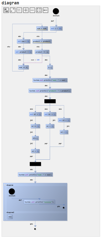
This one illustrates that the approach scales to reasonable sizes, shows that zooming is supported and also demonstrates the auto layouting capability. The graphical notation also integrates with things such as tooltips.
General Information
The definition of a graphical editor is based on the same “cell” abstraction used in other MPS editors: the language for defining editors contains additional cells that are then rendered as a diagram (diagram, diagram.box, diagram.edge). Similar to tables, these abstractions for defining graphical editors rely on queries to make sure that the structure of the graphical editor does not have to directly correspond to the structure of the AST (for example, in terms of ownership). The language also supports hierarchical diagrams, for example, in state machines.
To see example code, check out the MPS-Extensions examples here.
Diagram Creation Example – Step by Step
In the following section, a step by step guide for a simple friend relationship language is presented. You can find the source code for the example in this repository. If you are familiar with the diagram extension and search for a more advanced example, head over to dslfoundry.com where the MPS concept modeling is enhanced to be edited with the diagram editor. Another how-to based on the example shown later can be found under tillschallau.de
Concepts
For our small example we introduce three concepts fundamental for friendship requests in social networks. First we need the Person and FriendshipRequest concepts.
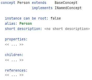
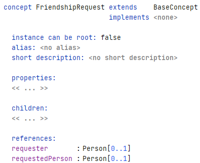
The Person concept is a simple concept implementing the INamedConcept interface which gives the concept a name attribute.
The concept FriendshipRequest functions as a connection between persons. Therefore it contains two references requester and requestedPerson, each one pointing to the person concept.
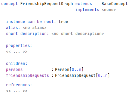
To glue these two concepts together to build a working diagram, a designated parent concept with a diagram editor is necessary. In this example the FriendshipRequestGraph concept is set to be the root concept and contains a list of ‘persons’ and ‘friendshipRequests’-relations as children.
With these concepts the basic structure is complete. The more interesting part of diagram creation is situated in the concepts’ editors.
Editors
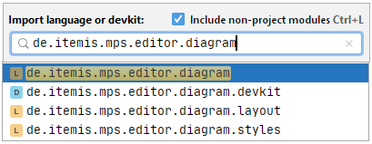
To get access to the diagram editor templates you have to import the de.itemis.mps.editor.diagram language. Either add it via the Model properties of the editor model, or by opening the Import language or devkit menu (Win: Ctrl+L, MacOs: ⌘+L). Make sure that the Include non-project modules checkbox is checked.
The import of said language gives you four editor templates usable to create diagrams in MPS. You can find the four available templates in the screenshot below.
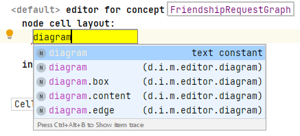
Three of these are explained in more detail with their respective concept instantiation.
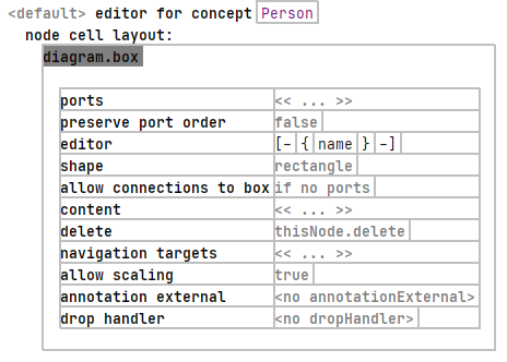
Let’s start by defining the editor for the Person concept. Each instance of this concept should be displayed as some sort of a shape (box, circle, triangle, stickfigure, etc.). The diagram language uses the diagram.box editor template to describe such representations. In the screenshot below the editor for the person concept is visualized. For the first example only the editor part is filled in. This field allows MPS cell models (such as node cells, collections, constants, etc.) to be entered. The property declaration of the node’s name is sufficient to demonstrate the editor’s effect on the diagram editor.
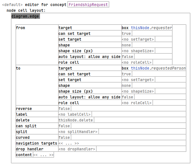
To display visual edges between persons, the de.itemis.mps.editor.diagram language uses the diagram.edge editor template. The minimum requirement to create edges is the declaration of from and to targets. As you can see in the screenshot below only these two fields are filled in. Note that you first have to declare the type of the target. It is possible to choose between box and port (where port is a designated part of a box, as you can see in the first feature screenshot at the beginning of this document) and an if decision. While the latter is only used to add more flexibility, the former are used to actually connect the edge to diagram objects. In our case we are connecting to boxes. To get the current FriendshipRequest concept the diagram language uses the reference thisNode. This reference is also used in the other editor templates. With this we can select our references requester and requestedPerson at their respective place.
To bring these editors together into a diagram editor, the overlying FriendshipRequestGraph concept needs its own editor.
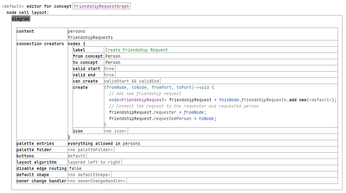
For this purpose the diagram editor template is introduced. Firstly we need to define the content of the diagram, by adding the children of the FriendshipRequestGraph concept persons and friendRequests to the content section. For a more in-depth view of the usage of query languages to add instances to the diagram refer to dslfoundry.com. The connection creators are necessary to synchronize the underlying model with its diagram representation. For this cause we have to specify between which concepts a specific edge can be created. In our example the from concept and to concept are the Person concept. The create field contains the information necessary for storing the change in the underlying model. To persist the newly added edge we have to create a new edge and assign the connected concepts to their respective references in the FriendshipRequest concept.
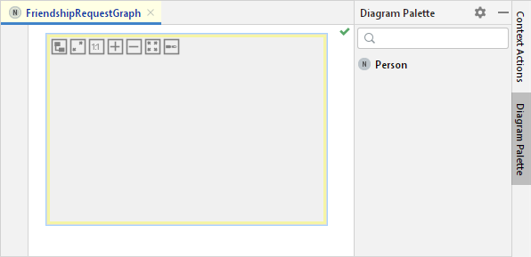
To complete the diagram editor, we add a palette entry. With this it is possible to drag and drop specific concepts onto the diagram, which are then automatically added to the underlying model. As edges are created by dragging-and-dropping, we only want the create Person concept instances with this method, therefore only these concept instances are allowed in the palette. The palette entries can be found on right side of your MPS IDE below the Context actions if you are in the editor of your diagram language, as you can see below.
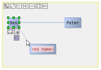
This concludes this small example with the following end result. You can see three Person boxes which were created by dragging them onto the diagram board from the diagram palette. The persons Ben and Peter have their name attribute already set, whereas the third person box still shows the editor for the property. To create an edge and therefore a relation between two persons, click on one person and click the button (the C under the box) highlighted in the screenshot. Dragging the edge connector to another node is then creating the edge.
This short introduction into the diagram language should get you to a point from which you can start making your own languages using diagrams. As already stated: for more exhaustive examples visit dslfoundry.com (query languages and graphical structure editor) and tillschallau.de (more complex structures and concepts, based on this how-to).