
This how-to is based on the introductory example MPS Diagrams that can be found here. There, a basic relationship structure is built from scratch with the usage of simple features of the de.itemis.mps.editor.diagrams language. In this how-to we are going to enhance the existing example with additional features, such as context hints and ports.
Recap
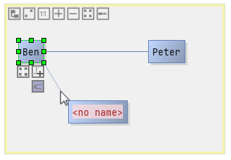
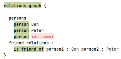
Let’s start by reminding ourselves of the previous example. Here we created a simple graph structure containing of the RelationsGraph, Person and IsFriendOf concepts with their respective editors. Below you can find the resulting diagram.
Context Hints
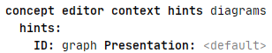
We start of by adding specialized context hints that enable the usage of multiple editors for the same underlying AST. Firstly create a new Context Hints node which can be found under the editor model. Enter a fitting name and then add a new hint. For our example we use graph as our hint id:
To use the specified hints in your modelling environment a unique editor has to be created for each hint that you want to use. The editors of our current example are using the default hint as you can see in the top left corner of the following screenshot.
By replacing the default hint with our newly created graph hint, the editor names are automatically updated to include the hint name; Person_Editor becomes Person_graph_Editor and so on. Looking at the instance of our language it now shows the default editor that MPS generates. The underlying AST remains unchanged but the presentation is now textual, as you can see in the following screenshot. You could change the style by defining new editors using the default hint to change the default presentation. This is out of the scope of this how-to and is described here.
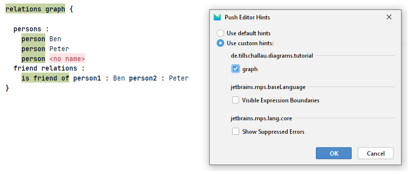
To switch to our graph visualization of the AST you have to open the Push Editor Hints menu, by right-clicking onto the projectional editor and selecting Push Editor Hints. In this menu select Use custom hints and then check the checkbox in front of graph. Clicking ok then applies the change and the diagram editor is shown again. With this process it is also possible to add multiple hints. The described menu is shown in the following screenshot.
Ports
The current modelling infrastructure allows for connection between Person and Person concepts as a friendship request relation. In some scenarios it is necessary to assign dedicated ports from which a connection can be created. This section will focus on simple ports to give a first example on how to use them in your language.
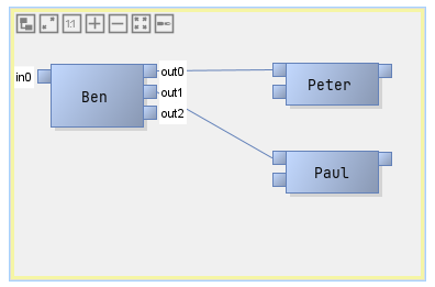
One example result model will could like this (the ports are shown, as the mouse cursor is moved over the Ben box):
Let’s put this example on top of the Person and FriendshipRequest concept. To model this behavior and display it as a graph of connected persons we have to introduce new concepts and additions to existing ones.
Ports can be modelled as separate concepts or as simple port names. To describe a more complex Port structure and how to embed it into the diagram we define the following FriendshipRequestPort concept.
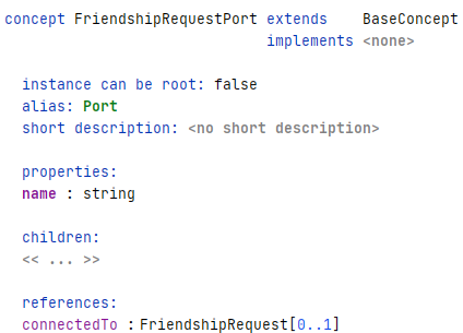
The name attribute is necessary to later reference the port. If you like you can add additional attributes in here but for the example the name is sufficient. To allow better navigation through the graph, a reference to the connected FriendshipRequest is also added. To connect the FriendshipRequest to the port internally we have to add the aforementioned references to the ports.
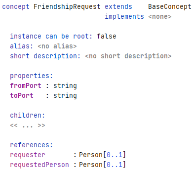
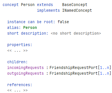
As Ports are referenced as strings/names the addition of two string properties is sufficient. To keep a list of ports for each node, we add incomingRequests and outgoingRequests as children to the Person concept.
With these changes the conceptual side of ports is completed. The more interesting part of updating the diagram editors is coming up next.
Let’s update the editor configuration of the FriendshipRequest concept first. To let edges connect to ports instead of boxes, the target in the diagram.edge editor has to be changed. In the following screenshot you can see the updated editor definition.
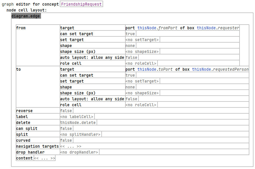
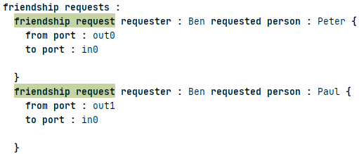
The properties thisNode.fromPort and thisNode.toPort we added earlier can be used here, to store the FriendshipRequestPort reference of the connected boxes thisNode.from and thisNode.to. Upon connecting two ports with each other, the port names are then stored in these properties. When inspecting an edge with the Reflective Editor the port references (i.e. their names) are set correctly as you can see in the following excerpt of the reflective editor of the final result. Here out0, in0, out1 and out2 are the names of the ports. The setting of these names follows in the next step.
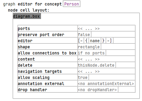
To actually display the ports for each Person box, its editor has to be adapted aswell. Looking back at the original Person editor from the first how-to, we only needed the editor aspect filled in. As we now want ports to be displayed, the ports aspect has to be complemented.
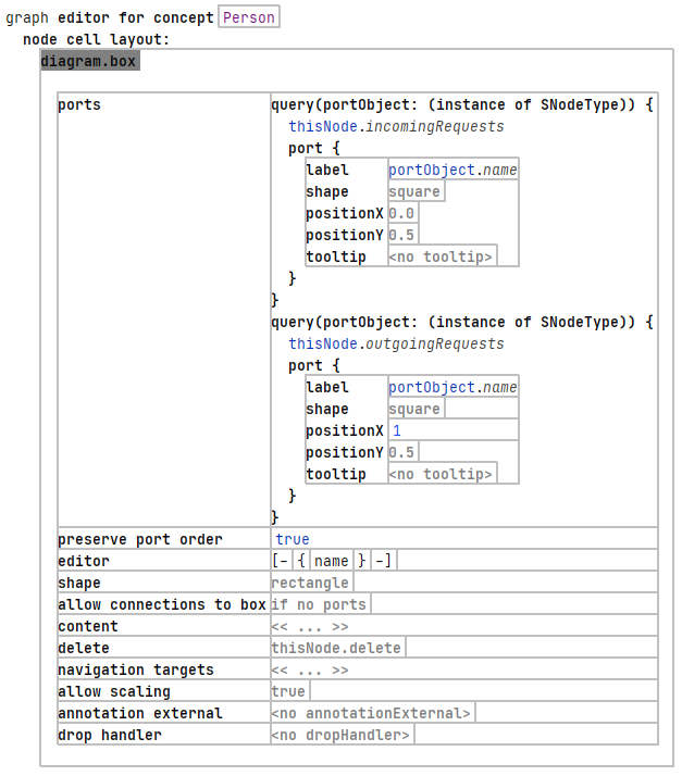
The Node concept contains two lists of ports, therefore we need two queries for each of the port lists. As the procedure is almost the same for both lists, the description of only one is sufficient. In the query aspect we have to declare the port query first. This can be a list of arbitrary types, in our case we pass the thisNode.incomingRequests list. The port{...} aspect will be applied for each port in the list separately. To get values of our list object, the current “iterator object” is given as portObject with the type defined in the query(...) header (i.e. SNodeType). First we have to provide the port’s label, which will be used as the reference (see previous step) for FriendshipRequests. The label is also used as a port name display, as can be seen in the final image at the beginning of this section (i.e. in0, out1, etc.). To use a different shape for ports the shape input can be used. An introduction to existing and custom made shapes will be available in another how-to. With the positionX and positionY inputs the position of the port can be determined. Note that 1 = 100% width/height of the box. Setting positionX to 0 results in attaching the port on the left side of the box (i.e. a value of 1 puts it on the right side). For a single port on each side these hardcoded values are fine but with more ports on each side a dynamic placement has to be considered. For example purposes a simple alignment algorithm can be found in the following screenshot.
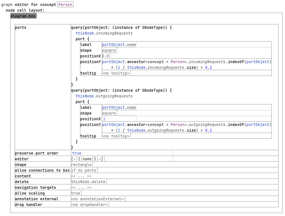
This code calculates the amount of ports on each side of the box and assigns each one an even distance to its neighbours. The ports are now configured correctly, now the persisting logic needs a final step. For this we update the FriendshipRequestGraph_graph_Editor with its conncetion creators.
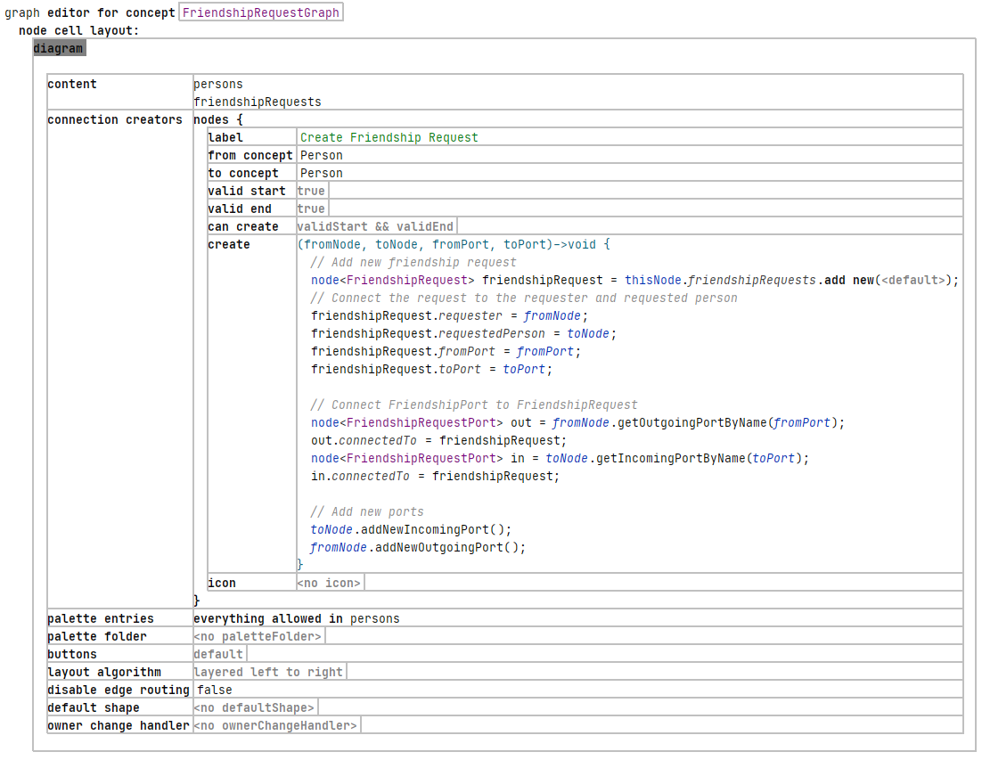
The excerpt above is the updated diagram editor of the introductory example. The properties fromPort and toPort of the newly created FriendshipRequest have to be set. To persist the connection on the port side as well, the connectedTo property of the two connected ports have to be set. The last two method calls toNode.addNewIncomingPort() and fromNode.addNewOutgoingPort() are optional and only cause the box to always create a new port upon connecting an edge to a box. This guarantees that there is always at least one free incoming- and outgoing-port per box.
The code for the used methods can be found below.

This completes the first part of the advanced how-to series for the JetBrains MPS Diagram language.